航空学报 > 2024, Vol. 45 Issue (11): 528826-528826   doi: 10.7527/S1000-6893.2023.28826

基于双目视觉和圆形标记点的发动机位移精确测试技术

高玉闪1,2(), 闫松1,2, 张志伟1,2   

  1. 1.西安航天动力研究所,西安 710100
    2.航天液体动力全国重点实验室,西安 710100
  • 收稿日期:2023-04-06 修回日期:2023-05-23 接受日期:2023-07-11 出版日期:2023-08-21 发布日期:2023-08-18
  • 通讯作者: 高玉闪 E-mail:gao_yushan@163.com

Precise engine displacement testing technique based on stereo vision and circular mark points

Yushan GAO1,2(), Song YAN1,2, Zhiwei ZHANG1,2   

  1. 1.Xi’an Aerospace Propulsion Institute,Xi’an  710100,China
    2.National Key Laboratory of Aerospace Liquid Propulsion,Xi’an  710100,China
  • Received:2023-04-06 Revised:2023-05-23 Accepted:2023-07-11 Online:2023-08-21 Published:2023-08-18
  • Contact: Yushan GAO E-mail:gao_yushan@163.com

摘要:

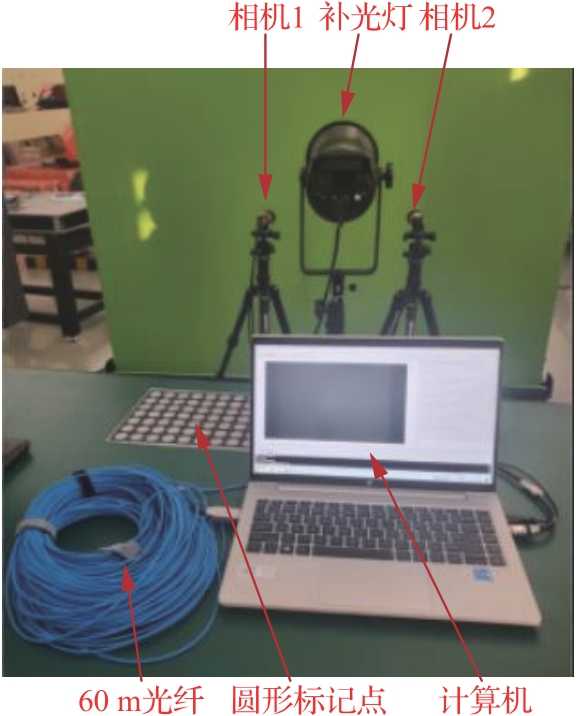
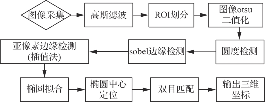
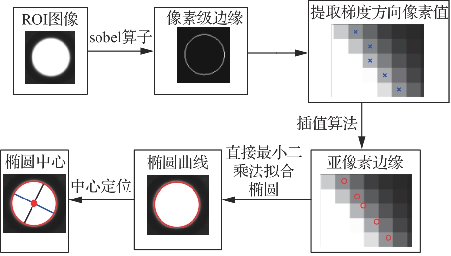
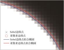
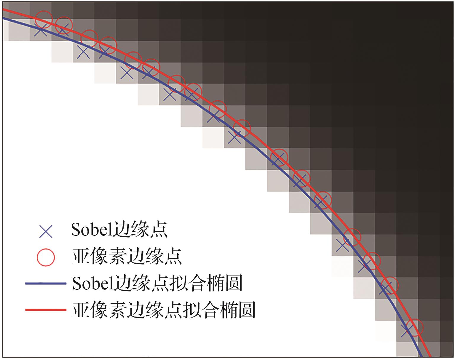
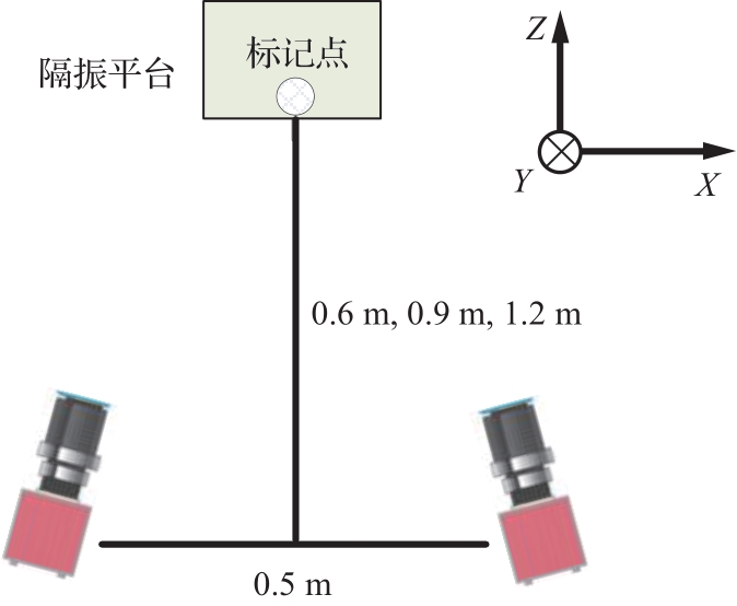
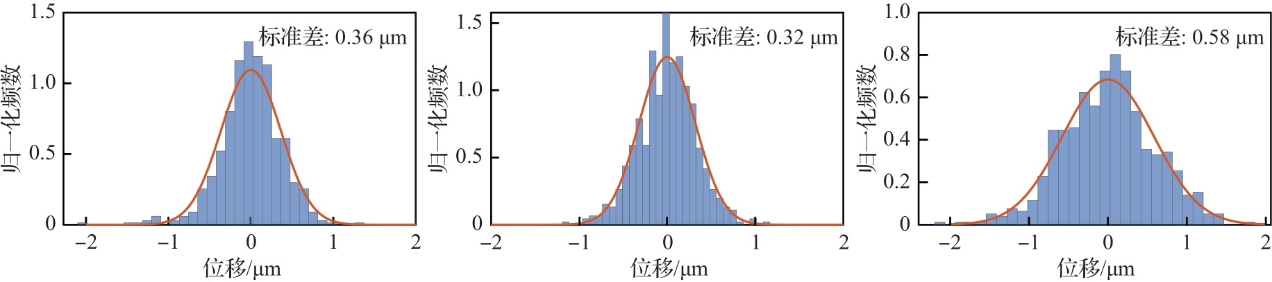
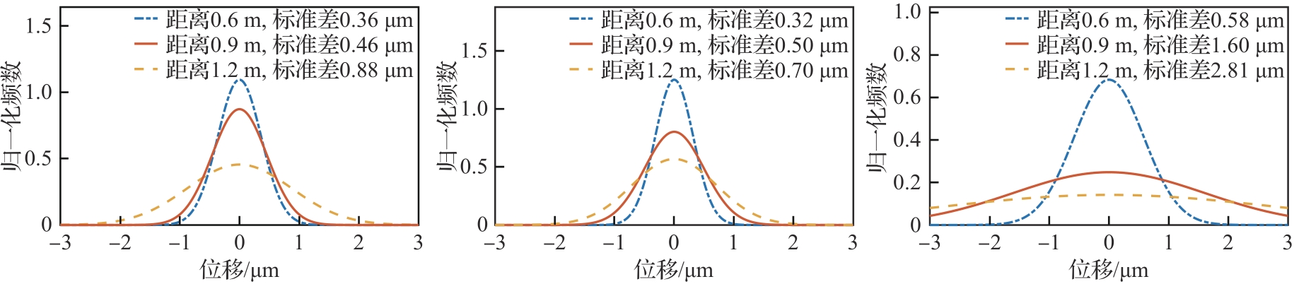
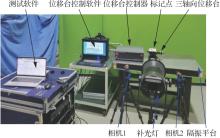
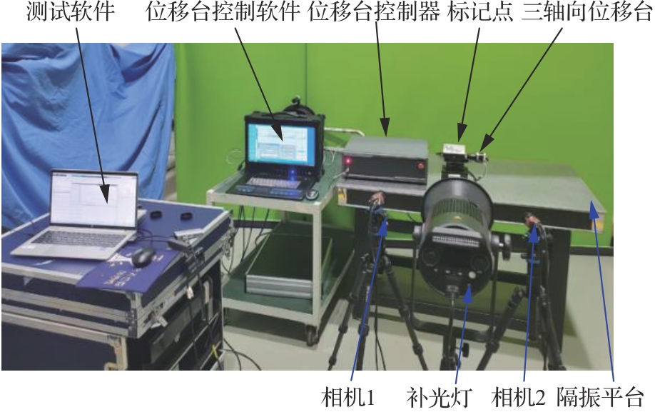
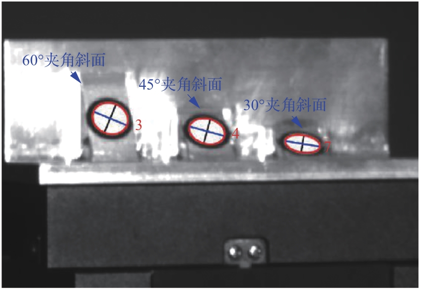
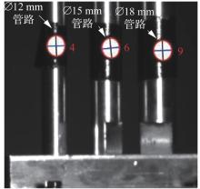
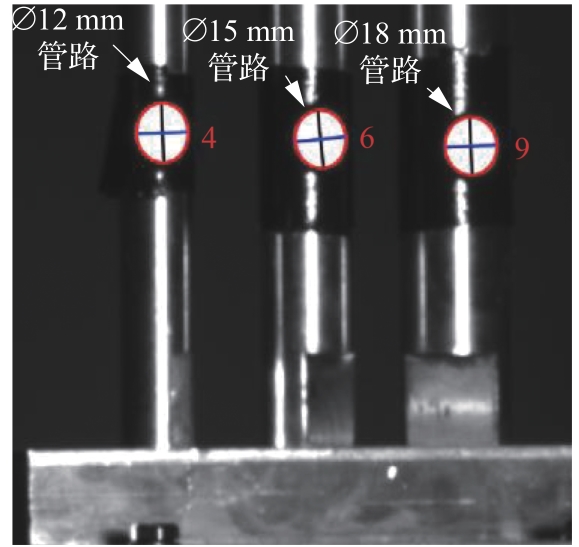
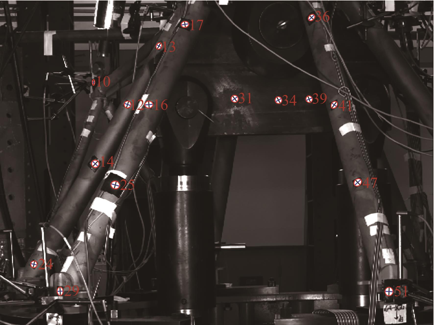
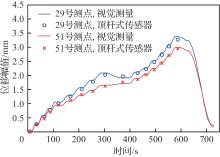
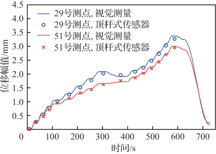
为了精确测量发动机静力试验和摇摆试验中结构的三维变形,提出一种基于双目视觉和圆形标记点的高精度位移测量方法,通过在发动机结构表面粘贴反光圆形标记点,并拍摄结构变形过程中的图像序列来识别位移。首先,使用Sobel边缘检测算法提取每个圆形标记点的像素级边缘信息;然后,通过基于插值的亚像素边缘检测方法获取亚像素级边缘点,以更准确地确定标记点的位置;最后,利用椭圆最小二乘法对标记点的边缘轮廓进行拟合,从而实现对标记点的精确定位。为了评估该方法的性能,对隔振云台上的静止标记点进行了位移测量。当相机距离标记点0.6 m时,面内2个方向的位移测量标准差分别为0.36 μm和0.32 μm,离面位移的测量标准差为0.58 μm。此外,通过使用位移台提供的标准位移,进一步验证了该算法在处理与相机平面夹角达60°斜面和∅12 mm细管路等结构位移测量时的适用性。将该视觉测量系统应用于某发动机机架的静力试验,取得了令人满意的结果。试验表明,该算法能够实时跟踪29个圆形标记点的位移,并且与电感式位移传感器测试结果的最大误差仅为5.6%。与传统的接触式位移测试方法相比,视觉测试方法具有布置迅速、成本低、测量精度高以及增加测量数量不会显著增加工作量等诸多优点,这使其成为一种替代传统位移测试的可靠且有效的方法。

关键词: 液体火箭发动机, 双目视觉, 圆形标记点, 亚像素, 位移

Abstract:

To accurately measure the three-dimensional deformation of the structure in engine static and swing tests, we propose a high-precision displacement measurement method based on stereo vision and circular markers. This method involves affixing reflective circular markers onto the engine structure surface and capturing a sequence of images during the structural deformation process. Firstly, the Sobel edge detection algorithm is used to extract the pixel-level edges of each circular marker. Then, an interpolation-based sub-pixel edge detection method is employed to obtain sub-pixel edge points, enabling more precise localization of the markers. Finally, the elliptical least squares fitting is applied to obtain the edge contours of the markers, thereby achieving accurate positioning. To evaluate the performance of this method, we conducted displacement measurements on stationary markers placed on a vibration isolation platform. When the camera was positioned 0.6 meters away from the markers, the standard deviations of in-plane displacements in two directions were found to be 0.36 μm and 0.32 μm, respectively, while that of out-of-plane displacement was 0.58 μm. Additionally, by using a displacement stage to provide standard displacements, we further validated the applicability of the algorithm in measuring the structure displacements with inclined surfaces at a 60° angle to the camera plane, as well as ∅12 mm small-diameter pipelines. The proposed visual measurement system was applied in a static test of an engine frame, yielding satisfactory results. The experiments demonstrated that the algorithm could track the displacements of 29 circular markers in real time, with a maximum error of 5.6% compared to an inductive displacement sensor. In comparison to traditional contact-based displacement testing methods, the visual testing method offers numerous advantages, including rapid setup, low cost, high measurement accuracy, and the ability to increase the measurement quantity without significantly increasing workload, making it a reliable and effective alternative to traditional displacement testing methods.

Key words: liquid rocket engines, stereo vision, circular marker, sub-pixel, displacement

中图分类号: