
1 高压捕获翼原理与构型
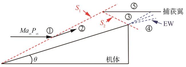
1.1 高压捕获翼基本设计原理
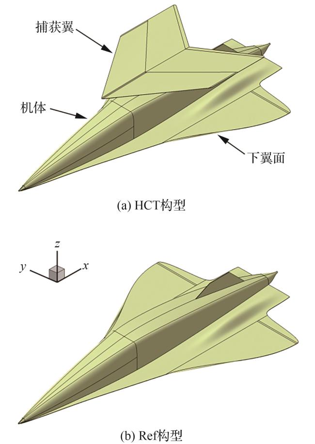
1.2 构型介绍
2 数值模拟方法与可靠性验证
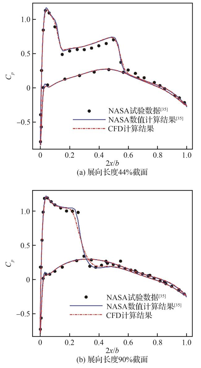
2.1 计算方法简介与计算验证
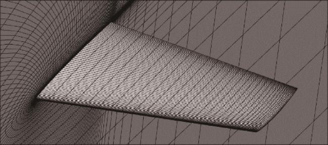
2.2 网格无关性验证
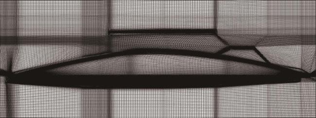
表1 网格无关性验证结果Table 1 Results of grid independence verification |
| Ma | 系数 | 粗网格 | 中等网格 | 细网格 |
|---|---|---|---|---|
| 0.8 | CL | 0.555 | 0.552 | 0.551 |
| CD | 0.071 0 | 0.073 1 | 0.073 8 | |
| Cmy | -0.321 | -0.318 | -0.317 | |
| 1.2 | CL | 0.600 | 0.594 | 0.593 |
| CD | 0.097 7 | 0.100 | 0.100 | |
| Cmy | -0.383 | -0.379 | -0.378 |
2.3 高超声速条件下基本特性验证
3 跨声速气动特性
3.1 计算工况
表2 计算工况Table 2 Computational conditions |
| Ma | H/km | Re/108 | α/(°) |
|---|---|---|---|
| 0.8 | 12 | 1.55 | -4, 0, 4, 6, 8, |
| 1.2 | 12 | 2.33 | 12, 16 |
3.2 Ma=0.8条件下流场结构和气动性能
3.2.1 流场结构特性
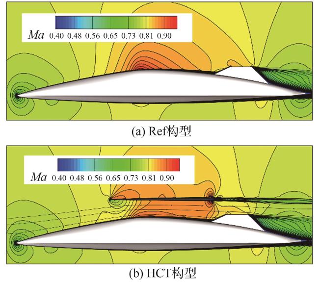
图 8 两种构型纵向对称面马赫数云图(Ma=0.8, α=4°)Fig.8 Mach number contours on longitudinal symmetry planes for both configurations (Ma=0.8, α=4°) |
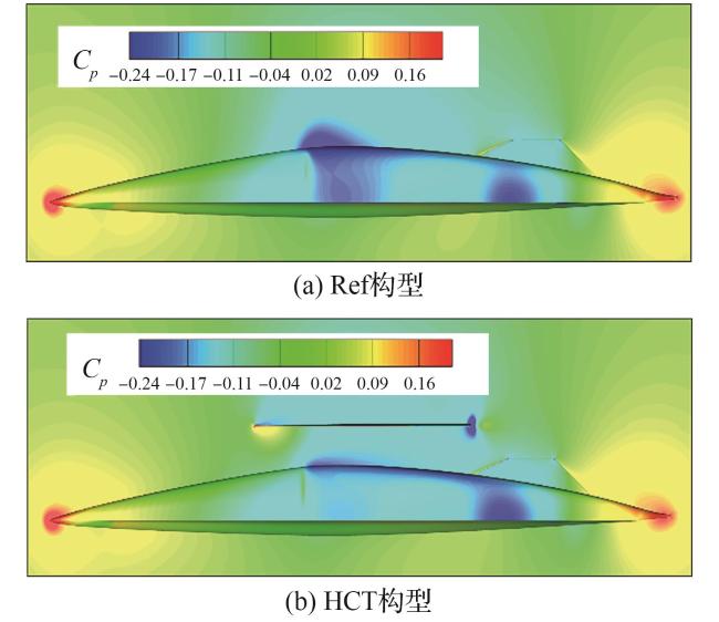
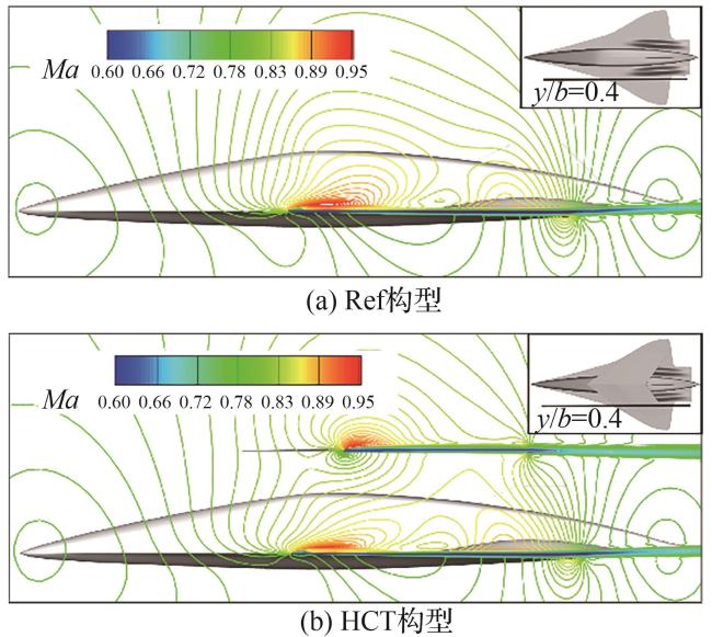
图 10 展向y/b=0.4处两种构型马赫数流线图(Ma=0.8, α=4°)Fig.10 Mach number streamlines at y/b=0.4 for both configurations (Ma=0.8, α=4°) |
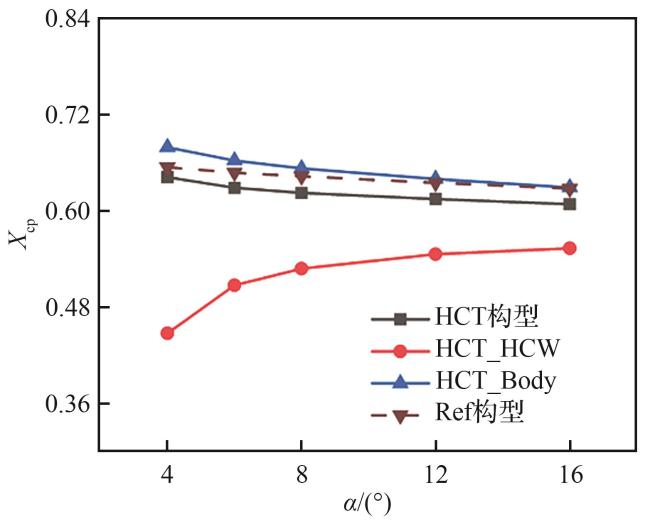
3.2.2 升、阻力与压心特性
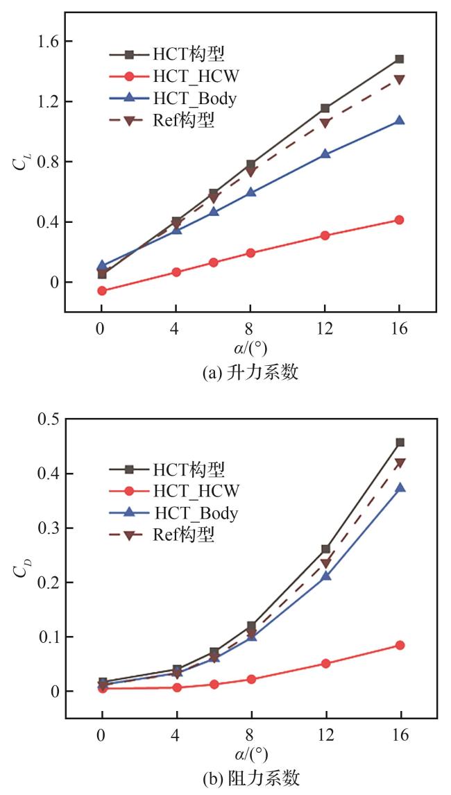
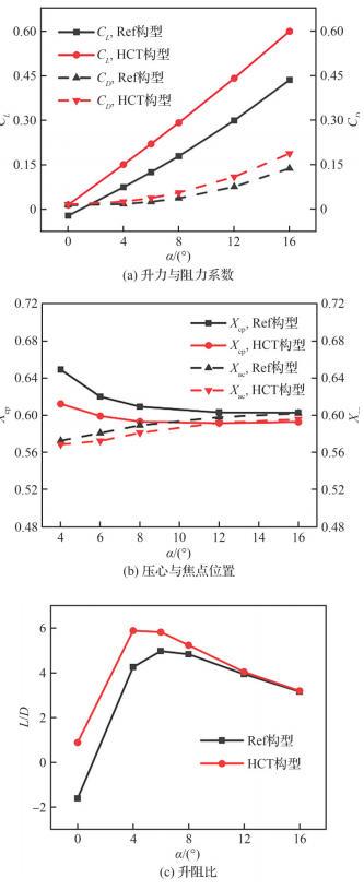
图 12 各部件升、阻力系数随攻角的变化曲线(Ma=0.8)Fig.12 Variation curves of lift and drag coefficients with angle of attack for individual components (Ma=0.8) |
3.3 Ma=1.2条件下流场结构和气动性能
3.3.1 流场结构特性
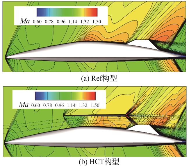
图 15 两种构型纵向对称面马赫数云图(Ma=1.2, α=4°)Fig.15 Mach number contours on longitudinal symmetry planes for both configurations (Ma=1.2, α=4°) |
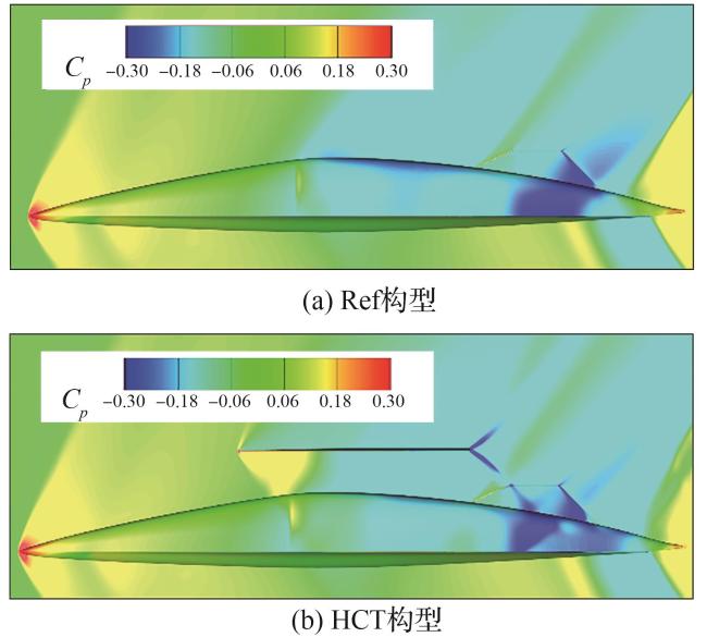
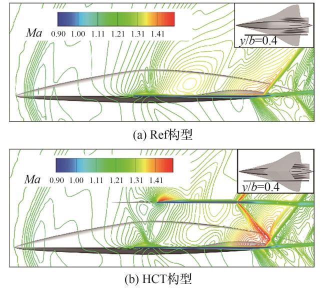
图 17 展向y/b=0.4处两种构型马赫数流线图(Ma=1.2, α=4°)Fig.17 Mach number streamlines at y/b=0.4 for both configurations (Ma=1.2, α=4°) |
3.3.2 升、阻力与压心特性
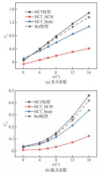
图 19 各部件升、阻力系数随攻角的变化曲线(Ma=1.2)Fig.19 Variation curves of lift and drag coefficients with angle of attack for individual components (Ma=1.2) |
3.4 宽速域气动焦点偏移比较
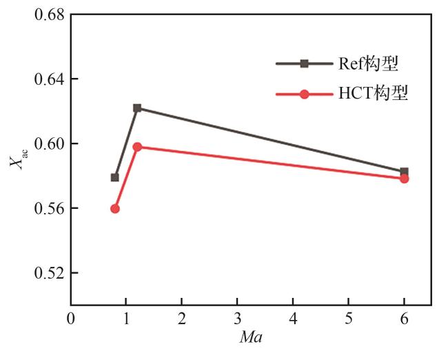
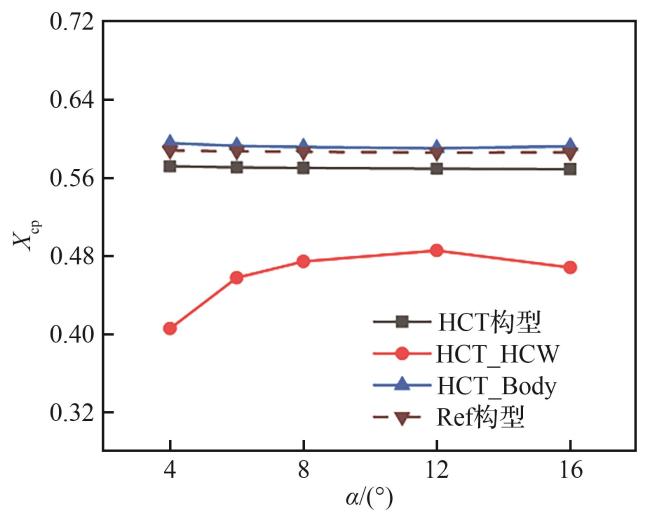
图 22 两种构型的焦点位置随马赫数的变化曲线Fig.22 Variation curves of aerodynamic center positions with Mach number for both configurations |
表3 两种构型在不同马赫数下的焦点位置Table 3 Aerodynamic center positions of both configurations at different Mach numbers |
| Ma | X ac | |
|---|---|---|
| Ref构型 | HCT构型 | |
| 0.8 | 0.578 7 | 0.559 6 |
| 1.2 | 0.621 8 | 0.597 9 |
| 6 | 0.582 5 | 0.578 2 |
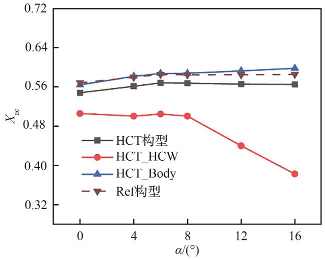
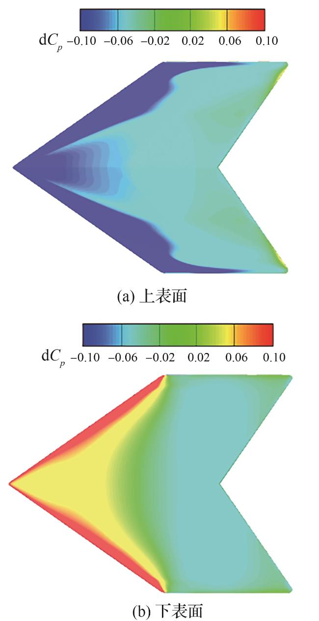
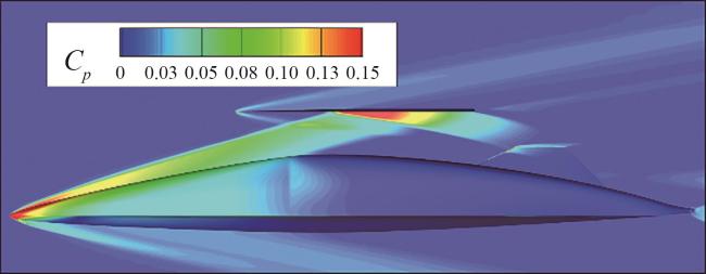
图 24 HCW上、下表面压力系数增量云图(Ma=0.8, α=4°)Fig.24 Pressure coefficient increment contours on upper and lower surfaces of HCW (Ma=0.8, α=4°) |
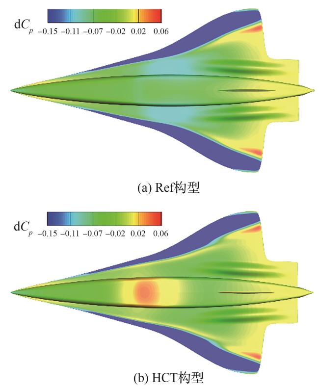
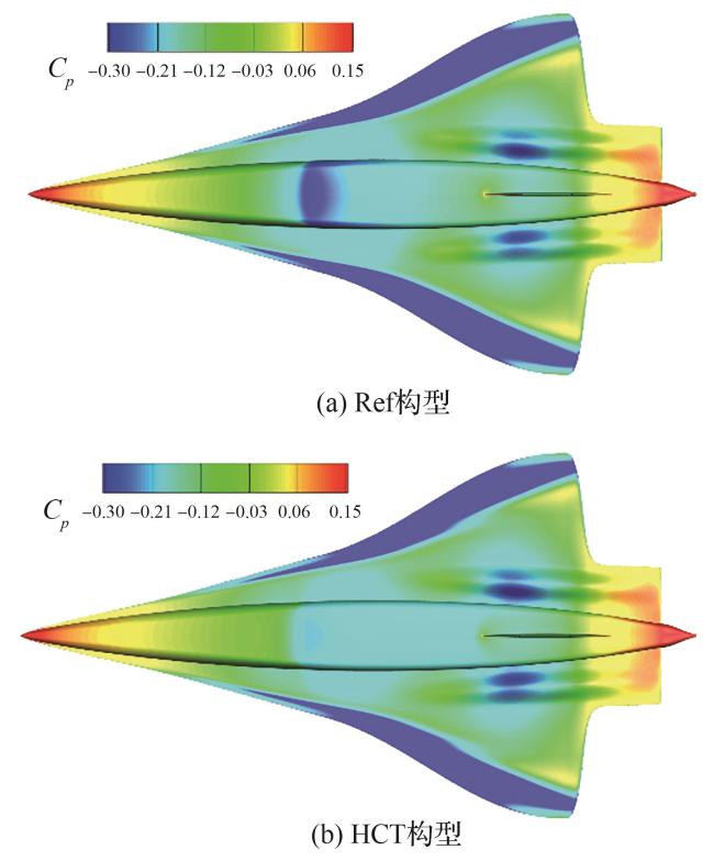
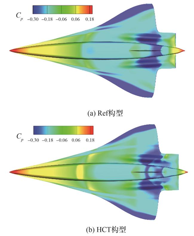
图 25 两种构型机体与下翼面的上表面压力系数增量云图(Ma=0.8, α=4°)Fig.25 Pressure coefficient increment contours on upper surfaces of fuselage and wing for both configurations (Ma=0.8, α=4°) |
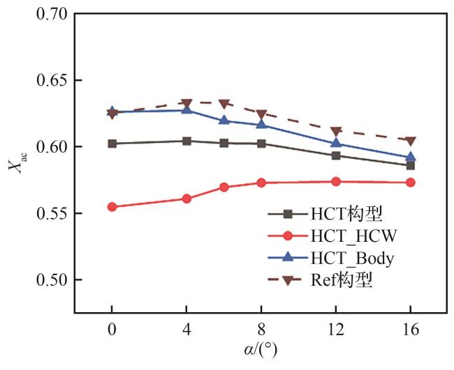
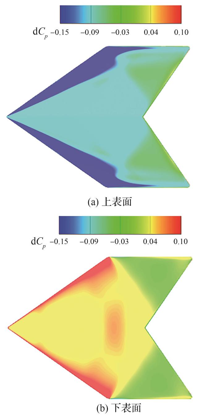
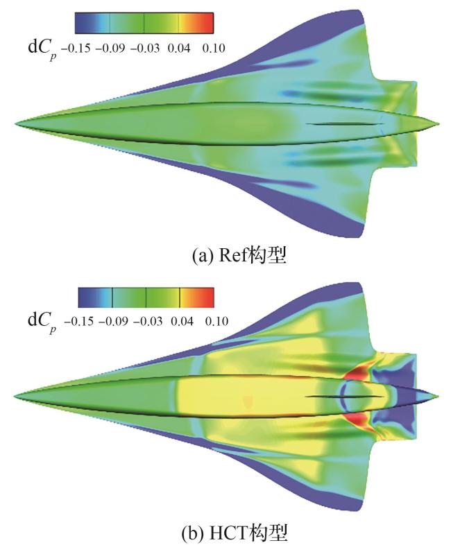
图 27 HCW上、下表面压力系数增量云图(Ma=1.2, α=4°)Fig.27 Pressure coefficient increment contours on upper and lower surfaces of HCW (Ma=1.2, α=4°) |